RENARD 16
The Renard 16 is a PIC microcontroller based Christmas light controller with 16 solid state relay circuits incorporated into the board. Dave (Xmus) designed the board based on the PIC-based 8-port dimmer concept originally developed by Phil Short. Information on the original concept can be viewed here. Generinc information pertaining to current Renard designs (including maximum channel count) can be found on the Renard wiki page.
A lot of great information on the Renard 16 can be found on Dave's website located here. The manual that Dave put together is very informative and a must read for anybody wanting to use the Renard 16. This page is not intended to replace Dave’s manual but is instead meant to present the basic info necessary to get a Renard 16 up-and-running.
Design
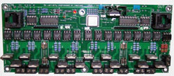
The board is a simple design, and follows the standard connection for an AC SSR COOP board. The RJ45 Socket provides the connection from the DC SSR to the Controller. The LED on the board indicates 5VDC is being supplied from the Controller to the OPTO.
The OPTO, which is different to the MCO3023M used on the AC SSR, is a K84PH, 16 pin DIP IC. I purchased mine from Mouser. 782-K847PH was the Mouser Part # and they cost $1.02 each, and here is the Datasheet The OPTO provides DC isolation from the Controller to the DC load. this is a safety feature, though some would suggest it could be deleted, I felt that will storms and electrical noise, it makes sense to isolate the PC and controller from the Lights.
The load switching is provided by MOSFETs.
The original MOSFET used was a STF20NF06. Mouser are no longer stocking this part. An alternate part is the FQPF13N06L.
There is a regulated 5V DC supply for the OPTOs, provided by either a 7805 or a 78L05 on the PCB. the PCB has mount holes for the TO-220 or TO-92 case style.
Euro style screw connectors are specificed for the board, and they are grouped in pairs (+/-) to make connections easy.
The DCSSR is designed to switch DC loads between 0 and 30 Volts. The MOSFETs are rated to 10 Amps each, however as fitted to the PCB, I would limit to individual channel load to 2 to 3 Amps max. A suitable heatsink will be required
Parts List
I have built a Parts List BOM in Mouser. Click here to load it.
| Label | Part | Description | Quanity |
|---|---|---|---|
| Q1-4 | 512-FQPF13N06L | MOSFET 60V N-Channel QFET Logic Level | 4 |
| 571-1-390261-4 | IC & Component Sockets 16P | 1 | |
| RJ45 | 571-5520251-4 | Ethernet Connectors 8/8 SIDE ENTRY | 1 |
| OPTO | 782-K847PH | K847PH Optocouplers Quad | 1 |
| R9-13 | 660-CF1/4C681J | Carbon Film Resistors - 680ohms 5% | 5 |
| R1-4 | 660-CF1/4C471J | Carbon Film Resistors - 470ohms 5% | 4 |
| R5-8 | 660-CF1/4C103J | Carbon Film Resistors - 10kohms 5% | 4 |
| LED | 604-WP7104IT | LED | 1 |
| U2 | 863-MC78L05ACPRPG | 78L05 Linear Reguator 5 V 100 mA | 1 |
| TB0-4 | 538-39890-0302 | Terminal Block 5.00 mm 2P 14-24 AWG | 5 |
| C1 | 80-C322C104Z5U | Capacitor - Leaded 50volts 0.1uF 20% | 1 |
| C2 | 80-C322C334M5U | Capacitor - Leaded 50volts 0.33uF 20% | 1 |
Printed Circuit Board
A circuit board for the DC SSR is available for sale.